Cessna Citation LongitudeMSFS 2024 Startup Checklist · 157 steps
Cessna Citation Longitude
MSFS 2024 - 0/157 STEPS
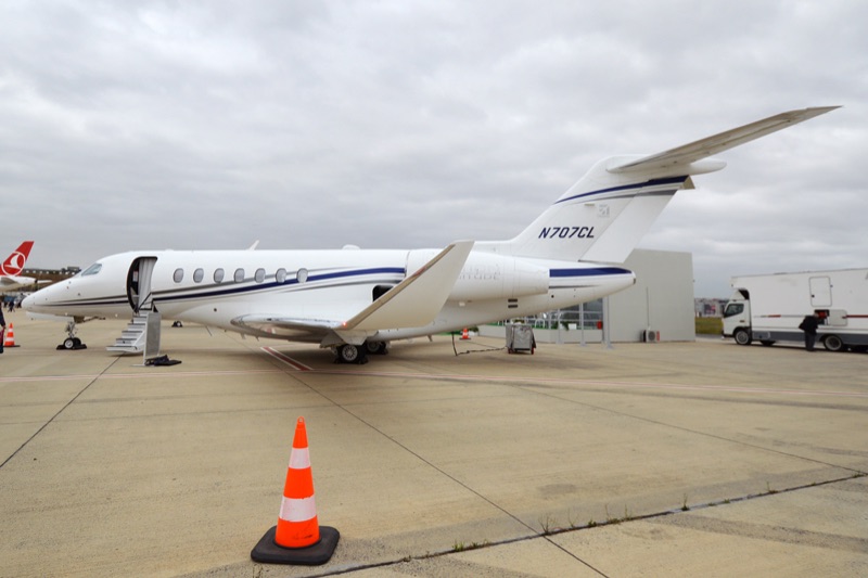
Wikimedia CommonsCC BY-SA 4.0
General AviationModern
AIRCRAFT BRIEF
The Cessna Citation Longitude is a super-midsize business jet developed by Textron Aviation, announced at EBACE 2012 and certified by the FAA on September 21, 2019 after its first flight on October 8, 2016. Powered by dual Honeywell HTF7700L FADEC-controlled turbofans and equipped with the Garmin G5000 integrated avionics suite, it offers a 3,500 nmi range and a service ceiling of 45,000 ft, competing directly with the Bombardier Challenger 350 and Gulfstream G280.
RANGE VISUALIZER
SPECIFICATIONS
manufacturerCessna (Textron Aviation)
first Flight2016
roleSuper-midsize business jet
crew2 pilots + up to 12 passengers
engines2x Honeywell HTF7700L (7,665 lbf each)
max Speed893 km/h (Mach 0.84 / 483 kts)
range6,482 km (3,500 nmi)
ceiling45,000 ft
weight17,917 kg (MTOW)
PHS 1 — Pre-Flight Planning8 steps
| 01 | Weather Briefing (METAR / TAF / Sigmet)NOTE: Check departure, enroute, destination, and alternate weather. Winds aloft critical for FL450 operations. | REVIEWED | |
| 02 | NOTAMs | REVIEWED | |
| 03 | OFP / SimBrief Flight Plan | LOADED | |
| 04 | Fuel PlanningNOTE: Cruise burn approx 2,000-2,400 lbs/hr total. Include alternate and 45-min reserve. Fuel capacity approx 14,500 lbs. | VERIFIED | |
| 05 | Weight and BalanceCAUTION: Verify TOW within limits. CG check - aft loading affects longitudinal stability. | WITHIN LIMITS | |
| 06 | SID / STAR / Approach Review | BRIEFED | |
| 07 | Performance - V1 / VR / V2NOTE: V-speeds from G5000 FMS performance page or Garmin FPL performance calculator. | CALCULATED | |
| 08 | MEL / CDL Items | CHECKED |
PHS 2 — Before Start21 steps
| 01 | Parking Brake | SET | |
| 02 | Battery SwitchNOTE: Main battery powers avionics bus. G5000 displays begin initializing. | ON | |
| 03 | External PowerNOTE: Use GPU to conserve battery during avionics initialization. | CONNECT (if available) | |
| 04 | G5000 AvionicsNOTE: Allow 90-120 seconds for full G5000 initialization. Verify all display units are active. | INITIALIZING - ALL PFD/MFD DISPLAYS POWERING UP | |
| 05 | AHRS / Air DataNOTE: Verify PFD attitude and heading are valid. Cross-check with standby instruments. | VALID - CHECK ATTITUDE AND ALTIMETER | |
| 06 | G5000 - Flight PlanNOTE: Load departure, route, STAR, and approach into G5000 FMS. Verify origin and destination. | ENTER ROUTE | |
| 07 | G5000 - PerformanceNOTE: Enter actual TOW and conditions to compute V-speeds, climb performance, and fuel predictions. | ENTER WEIGHT AND CONDITIONS | |
| 08 | Altimeter (PFD) | SET QNH | |
| 09 | Standby Altimeter | SET QNH | |
| 10 | Fuel QuantityNOTE: Confirm fuel on both G5000 fuel page and physical fuel quantity gauges. | CHECK - VERIFY QUANTITY MATCHES PLAN | |
| 11 | Circuit Breakers | CHECK - ALL IN | |
| 12 | Flight Controls | FREE AND CORRECT | |
| 13 | Trim | SET FOR TAKEOFF (as computed by FMS) | |
| 14 | Flaps | 2 (15 deg for normal takeoff) | |
| 15 | Pressurization | SET DESTINATION ELEVATION - AUTO MODE | |
| 16 | Oxygen PressureNOTE: Verify crew oxygen pressure is sufficient for FL450 operations. | CHECK - ADEQUATE FOR PLANNED ALTITUDE | |
| 17 | Passenger Briefing | COMPLETE | |
| 18 | DoorsCAUTION: Verify main cabin door and baggage doors are secure before APU and engine start. | CLOSED AND LOCKED | |
| 19 | Seatbelts | FASTENED - ALL ABOARD | |
| 20 | Beacon Light | ON | |
| 21 | GSX - Fuel TruckNOTE: GSX menu: Refuel Aircraft. Set desired fuel load before confirming. | REFUEL COMPLETE |
PHS 3 — APU Start5 steps
| 01 | APU Master Switch | ON | |
| 02 | APU Start SwitchNOTE: Hold momentarily to initiate APU start sequence. | START | |
| 03 | APU - Monitor StartNOTE: Allow approximately 1-2 minutes for APU to reach operating parameters. | RUNNING - AVAIL LIGHT ON | |
| 04 | APU Bleed AirCAUTION: Engine start requires minimum 32 PSI APU bleed pressure. Do not attempt engine start below this pressure. | ON - VERIFY 32 PSI MIN | |
| 05 | External Power | DISCONNECT (if used - APU now supplying power) |
PHS 4 — Engine Start12 steps
| 01 | Throttles (both) | CUTOFF / OFF | |
| 02 | Left Engine - FADEC Switch | RUN | |
| 03 | Left Engine - Starter SwitchNOTE: Hold starter switch for approximately 2 seconds until ignition is established. FADEC handles fuel scheduling automatically. | HOLD 2 SECONDS UNTIL IGNITION | |
| 04 | Left Engine - N1/N2 RisingNOTE: Watch N1 and N2 rise. FADEC manages ignition and fuel flow throughout start. | MONITOR - INCREASING | |
| 05 | Left Engine - ITTWARNING: ITT limit during start is 955 deg C. FADEC should prevent exceedance but monitor closely. If ITT approaches limit, FADEC switch to STOP immediately. | MONITOR - MAX 955 DEG C | |
| 06 | Left Engine - N1 IdleNOTE: Engine stabilizes at ground idle. Allow parameters to settle before checking. | STABILIZE AT GROUND IDLE (~22% N1) | |
| 07 | Left Engine - Oil PressureCAUTION: If oil pressure not in range within 30 seconds, FADEC switch to STOP. Investigate before attempting another start. | IN GREEN BAND (within 30 seconds) | |
| 08 | Right Engine - FADEC Switch | RUN | |
| 09 | Right Engine - Starter Switch | HOLD 2 SECONDS UNTIL IGNITION | |
| 10 | Right Engine - N1/N2 and ITT | MONITOR - SAME LIMITS APPLY | |
| 11 | Right Engine - Oil Pressure | IN GREEN BAND (within 30 seconds) | |
| 12 | Both Engines - Idle CheckNOTE: Verify both engines settled at idle with no cautions on G5000 engine display. | N1, N2, ITT, OIL ALL WITHIN LIMITS |
PHS 5 — After Start9 steps
| 01 | APU Bleed AirNOTE: Turn off APU bleed air once both engines are running. | OFF (engines now supplying bleed) | |
| 02 | APUNOTE: APU can be shut down now or left running per company SOP. | OFF or LEAVE RUNNING (as required) | |
| 03 | Generators (L and R)NOTE: Both engine generators should be online. Check electrical synoptic for bus voltages. | ON LINE - VERIFY | |
| 04 | Anti-Ice | SET AS REQUIRED FOR CONDITIONS | |
| 05 | Transponder | SET SQUAWK CODE - STBY | |
| 06 | Radios | SET ATIS AND GROUND FREQUENCIES | |
| 07 | ATIS | RECEIVED AND NOTED | |
| 08 | G5000 - FMS Route | VERIFY ACTIVE - CONFIRM WAYPOINTS | |
| 09 | Autopilot / AutothrottleNOTE: Verify autopilot and autothrottle pre-engage modes. Do not engage for takeoff. | PRE-FLIGHT MODE CHECK |
PHS 6 — Taxi7 steps
| 01 | Parking Brake | RELEASE | |
| 02 | Taxi Light | ON | |
| 03 | Navigation Lights | ON | |
| 04 | Brakes | CHECK - during first movement | |
| 05 | Nosewheel Steering | RESPONSIVE | |
| 06 | Taxi SpeedNOTE: Reduce speed well before turns. Longer wheelbase requires wider turns than smaller jets. | NORMAL TAXI PACE | |
| 07 | Transponder | ALT MODE (as required by local procedures) |
PHS 7 — Before Takeoff13 steps
| 01 | Parking Brake | SET (hold short) | |
| 02 | Flight Controls | VERIFY FREE AND CORRECT | |
| 03 | Trim | CONFIRM TAKEOFF SETTING | |
| 04 | FlapsNOTE: Verify flap setting on G5000 synoptic page. Flaps 2 (15 deg) is standard takeoff configuration. | 2 (15 deg) CONFIRM | |
| 05 | G5000 - V-SpeedsNOTE: Confirm V1, Vr, and V2 bugs are set on PFD airspeed tape. | VERIFY V1 / VR / V2 DISPLAYED | |
| 06 | Transponder | ALT (Mode C - active) | |
| 07 | Pressurization | AUTO - DESTINATION SET - CHECK | |
| 08 | Lights | STROBE ON, LANDING LIGHT ON | |
| 09 | Doors | CLOSED AND LOCKED - CONFIRM | |
| 10 | Seatbelts | FASTENED - ALL ABOARD | |
| 11 | Engine Instruments | CHECK BOTH ENGINES NORMAL | |
| 12 | Departure BriefingNOTE: Brief SID, initial climb altitude, engine failure action, abort criteria. | COMPLETE | |
| 13 | ATC Clearance | RECEIVED |
PHS 8 — Takeoff10 steps
| 01 | Runway Alignment | CONFIRM ASSIGNED RUNWAY | |
| 02 | ThrottlesNOTE: Advance both throttles smoothly to TOGA detent. FADEC manages thrust to rating limits automatically. | ADVANCE SMOOTHLY TO TOGA | |
| 03 | Engine Instruments | BOTH ENGINES SYMMETRIC - N1 ON BUGS | |
| 04 | Brakes | RELEASE | |
| 05 | 80 KnotsNOTE: At 80 kts call 80 kts. Verify airspeed alive, attitude normal, engine instruments normal. | CALL - INSTRUMENTS CHECKED | |
| 06 | V1CAUTION: Do NOT abort after V1 unless catastrophic failure. Below V1 abort is pilot's prerogative. | CALL V1 - COMMIT TO TAKEOFF | |
| 07 | Rotation (Vr)NOTE: Apply steady back pressure at Vr. Rotate smoothly - avoid jerky inputs. Target 10-12 degrees pitch. | ROTATE SMOOTHLY to 10-12 DEG NOSE UP | |
| 08 | Positive Rate | CONFIRM CLIMB RATE POSITIVE | |
| 09 | Landing GearCAUTION: Raise gear at positive rate. Gear limit speed 250 kts - ensure gear up before speed build. | UP (positive rate confirmed) | |
| 10 | Pitch | MAINTAIN V2 + 10 UNTIL 1,000 FT AGL |
PHS 9 — After Takeoff / Climb8 steps
| 01 | FlapsNOTE: Retract flaps progressively: Flaps 1 then Clean at appropriate speeds and altitude (400+ ft AGL, above flap retraction speeds). | RETRACT ON SCHEDULE | |
| 02 | ThrottlesNOTE: Reduce from TOGA to climb thrust at 1,000 ft AGL or per SID. FADEC manages climb rating. | REDUCE FROM TOGA TO CLB at 1,000 ft AGL | |
| 03 | AutopilotNOTE: Engage autopilot in heading and VS or FLC mode. Select NAV for lateral FMS guidance. | ENGAGE (if desired above 400 ft AGL) | |
| 04 | AutothrottleNOTE: Engage autothrottle in speed mode to maintain target climb speed. | ENGAGE - SPEED MODE | |
| 05 | Pressurization | CHECK - CABIN PRESSURIZING NORMALLY | |
| 06 | Engine Instruments | PERIODIC CHECKS - ALL WITHIN LIMITS | |
| 07 | AltimeterNOTE: Set standard pressure at transition altitude (18,000 ft US). Coordinate with ATC. | SET 29.92 AT TRANSITION ALTITUDE | |
| 08 | Anti-Ice | AS REQUIRED FOR CONDITIONS |
PHS 10 — Cruise8 steps
| 01 | Cruise AltitudeNOTE: Typical cruise FL410-FL450. Citation Longitude certified to FL450. | LEVEL OFF - AUTOPILOT ON ALTITUDE | |
| 02 | Throttles | AUTOTHROTTLE MANAGES MACH 0.82-0.84 | |
| 03 | PressurizationNOTE: At FL450, cabin altitude should be approximately 5,950 ft. Max differential 9.66 PSI. | CHECK - CABIN ALTITUDE BELOW 6,000 FT | |
| 04 | Fuel Quantity | CHECK - BURN CONSISTENT WITH PLAN | |
| 05 | G5000 - Navigation | VERIFY WAYPOINTS, ETA, FUEL PREDICTION | |
| 06 | Radios | SET ENROUTE FREQUENCIES | |
| 07 | Anti-Ice | AS REQUIRED | |
| 08 | Top of DescentNOTE: At FL450, begin planning descent approximately 130-140 nmi out (3 nmi per 1,000 ft). | CALCULATE |
PHS 11 — Descent9 steps
| 01 | ATIS / Destination Weather | OBTAIN | |
| 02 | G5000 - Arrival / Approach | ENTER STAR AND APPROACH PROCEDURE | |
| 03 | Altimeter | SET DESTINATION QNH (below transition) | |
| 04 | Descent SpeedNOTE: Autothrottle manages descent speed. Target cross-checks against VNAV profile. | MACH 0.82 THEN 280-300 KIAS BELOW FL280 | |
| 05 | Throttles | IDLE / AUTOTHROTTLE MANAGED | |
| 06 | Pressurization | CHECK - CABIN DESCENDING | |
| 07 | Fuel | CHECK REMAINING vs. DESTINATION PLUS ALTERNATE | |
| 08 | Seatbelt Sign | ON - NOTIFY PASSENGERS | |
| 09 | Anti-Ice | AS REQUIRED FOR CONDITIONS |
PHS 12 — Approach11 steps
| 01 | Approach BriefingNOTE: Brief approach type, DA/MDA, missed approach procedure, runway, and emergency actions. | COMPLETE | |
| 02 | Altimeter | SET QNH - CROSS-CHECK BOTH PFDs | |
| 03 | G5000 - Approach Active | APPROACH LOADED AND ACTIVATED | |
| 04 | AutopilotNOTE: Verify autopilot is in approach mode for coupled ILS. Localizer and glideslope armed on PFD. | APPROACH MODE (APP) - ARMED | |
| 05 | FlapsNOTE: Select flaps 1 entering approach. Verify Vfe not exceeded. | 1 (7 deg) - INITIAL APPROACH | |
| 06 | Landing GearNOTE: Extend gear at or below 250 kts. Verify 3 green down-and-locked lights. | DOWN - 3 GREEN | |
| 07 | FlapsNOTE: Select full flaps on final below 140 kts. Verify on G5000 synoptic page. | FULL (35 deg) - FINAL APPROACH | |
| 08 | Approach Speed | VREF + WIND ADDITIVE (128-135 KIAS typical) | |
| 09 | Stabilized ApproachCAUTION: If approach is not stabilized (on speed, on path, correct configuration) by 500 ft AGL, execute go-around. | CONFIRM BY 500 FT AGL | |
| 10 | Landing Light | ON | |
| 11 | Autobrake | SET (MEDIUM for normal) |
PHS 13 — Landing8 steps
| 01 | Final Approach Speed | VAPP - MAINTAINED TO THRESHOLD | |
| 02 | AutopilotNOTE: Disconnect autopilot at or before decision height. Hand-fly to touchdown. | DISCONNECT AT MINIMUMS (or fly manually from final) | |
| 03 | FlareNOTE: Begin gentle flare at approximately 30-40 ft AGL. Reduce throttles to idle as aircraft flares. | GENTLE AT 30-40 FT AGL - REDUCE THRUST | |
| 04 | TouchdownNOTE: Let main gear touch first, then ease nosewheel to runway. Firm touchdown is preferable to long float. | MAIN GEAR FIRST - FIRM | |
| 05 | Thrust ReversersNOTE: Select thrust reversers on touchdown. Stow before 60 kts. | DEPLOY - MAXIMUM | |
| 06 | Ground SpoilersNOTE: Ground spoilers deploy automatically on touchdown. Verify spoiler deployment on G5000. | AUTO DEPLOY | |
| 07 | BrakesNOTE: Autobrake system manages deceleration. Apply manual brakes if autobrake fails to activate. | AUTOBRAKE or MANUAL BRAKING | |
| 08 | Thrust ReversersCAUTION: Stow reversers before speed drops to 60 kts to avoid foreign object ingestion and thrust asymmetry. | STOW BEFORE 60 KTAS |
PHS 14 — After Landing8 steps
| 01 | FlapsNOTE: Retract flaps after clearing runway. | RETRACT TO UP | |
| 02 | Ground Spoilers | RETRACTED - VERIFY | |
| 03 | Landing Light | OFF | |
| 04 | Strobe Lights | OFF | |
| 05 | Taxi Light | ON | |
| 06 | Transponder | STBY (or as instructed) | |
| 07 | Anti-Ice | AS REQUIRED | |
| 08 | Taxi Clearance | RECEIVE - CONTACT GROUND |
PHS 15 — Parking / Shutdown20 steps
| 01 | Parking Brake | SET | |
| 02 | ThrottlesCAUTION: Do not shut down HTF7700L engines immediately after high-power operations. Heat soak can cause turbine distortion.NOTE: Allow engines to cool at idle for 3 minutes minimum after flight. Prevents thermal damage to hot section. | IDLE - ALLOW 3-MINUTE COOL-DOWN | |
| 03 | APUNOTE: Start APU before engine shutdown to maintain electrical power for avionics, pressurization. | START (if external power not available) | |
| 04 | Lights | LANDING AND STROBE OFF - TAXI AS REQUIRED | |
| 05 | PressurizationNOTE: Verify cabin pressure equals ambient before opening door. | EQUALIZE - DEPRESSURIZE | |
| 06 | Avionics | SHUT DOWN (avionics master off before fuel cutoff) | |
| 07 | Anti-Ice | OFF | |
| 08 | Left Engine - FADEC Switch | STOP (CUTOFF) | |
| 09 | Right Engine - FADEC Switch | STOP (CUTOFF) | |
| 10 | Engine Spool-Down | MONITOR N1/N2 DECREASING | |
| 11 | Generators | OFF (when N1 below 15%) | |
| 12 | APU | OFF (when ground power connected) or LEAVE RUNNING | |
| 13 | Battery | OFF | |
| 14 | Beacon Light | OFF (after engines stopped) | |
| 15 | Navigation Lights | OFF | |
| 16 | Fuel Shutoff | CONFIRM CLOSED | |
| 17 | Passenger DeplaningNOTE: Verify cabin has fully depressurized before opening main cabin door. | DOOR OPEN WHEN PRESSURE EQUALIZED | |
| 18 | Post-Flight LogNOTE: Log flight time, fuel used, landings, and any discrepancies. | COMPLETE | |
| 19 | Securing | PITOT COVERS, CHOCKS INSTALLED | |
| 20 | GSX - Ground Power Unit (GPU)NOTE: GSX menu: Ground Power Unit. GPU availability varies by airport. | CONNECT (if available) |