Airbus H125MSFS 2024 Startup Checklist · 144 steps
Airbus H125
MSFS 2024 - 0/144 STEPS
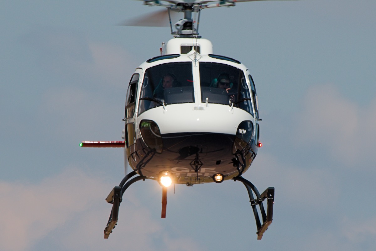
Airwolfhound / Wikimedia CommonsCC BY-SA 2.0
RotaryModern
AIRCRAFT BRIEF
The Airbus H125 (formerly Eurocopter AS350 Écureuil/AStar) is the world's most popular single-engine helicopter, with over 5,400 delivered since 1975. Powered by the Safran Arriel 2D engine, it is renowned for its exceptional high-altitude performance - in 2005, an AS350 B3 landed on the summit of Mount Everest at 8,848 meters. It serves in roles ranging from utility and EMS to law enforcement and VIP transport worldwide.
RANGE VISUALIZER
SPECIFICATIONS
manufacturerAirbus Helicopters
first Flight1974
roleLight utility helicopter
crew1 pilot + 5 passengers
engines1x Safran Arriel 2D (847 shp)
max Speed287 km/h (155 kts)
range630 km (340 nmi)
ceiling23,000 ft
weight2,250 kg (MTOW)
PHS 1 — Pre-Flight Planning10 steps
| 01 | Mission BriefNOTE: Define mission type, objectives, landing zones, and passenger/cargo requirements. | REVIEWED | |
| 02 | Weather Briefing (METAR / TAF / Winds Aloft)NOTE: Wind is critical for helicopter ops. Check for gusts, crosswind limits, and turbulence. Max demonstrated crosswind: 25 kt. | REVIEWED | |
| 03 | NOTAMs / Airspace RestrictionsNOTE: Check for TFRs, restricted areas, and heliport NOTAMs along route. | REVIEWED | |
| 04 | Fuel Planning - Endurance & Hover TimeNOTE: Fuel capacity 540 L (143 US gal). Burn rate ~210 L/hr cruise. Plan for 20-min VFR fuel reserve plus hover time at destination. | CALCULATED | |
| 05 | Weight & Balance / PayloadCAUTION: Max takeoff weight 2,250 kg (4,960 lbs). CG limits are narrow - verify with loading chart for all passenger and cargo configurations. | WITHIN LIMITS | |
| 06 | Performance Planning - Density Altitude / Hover CeilingWARNING: High density altitude significantly reduces hover ceiling and power available. Check OGE/IGE hover capability for departure and destination LZs. | CALCULATED | |
| 07 | Route / Landing Zone SurveyNOTE: Identify approach/departure paths, obstacles, terrain, and alternate landing sites along route. | REVIEWED | |
| 08 | Radio FrequenciesNOTE: Set tower, approach, CTAF, and destination frequencies. Note emergency frequency 121.5. | SET | |
| 09 | Passenger / Crew BriefingNOTE: Brief on entry/exit procedures (approach from front only), seatbelts, headset use, emergency exits, and no smoking. | COMPLETED | |
| 10 | GSX - Fuel TruckNOTE: GSX menu: Refuel Aircraft. Note: GSX fuel support varies by airport and helipad. | REFUEL COMPLETE |
PHS 2 — Cockpit Preparation / Before Start16 steps
| 01 | Rotor AreaWARNING: Ensure all persons and obstacles are clear of the rotor disc before any start. | CLEAR | |
| 02 | Doors | CLOSED AND LATCHED | |
| 03 | Seats / Harnesses | ADJUSTED AND LOCKED | |
| 04 | Circuit Breakers | CHECK ALL IN | |
| 05 | Collective | FULL DOWN AND LOCKED | |
| 06 | Twist Grip (Throttle)NOTE: Verify twist grip is in the full OFF (closed) position. | OFF | |
| 07 | Fuel Valve | ON | |
| 08 | Battery Master Switch | ON | |
| 09 | VEMDNOTE: Vehicle and Engine Multifunction Display powers up and completes self-test. Verify no fault codes. | CHECK INITIALIZATION | |
| 10 | Fuel QuantityNOTE: Verify fuel quantity on VEMD matches planned fuel load. | CHECK - Adequate for mission | |
| 11 | Caution / Warning PanelNOTE: Press test button. All lights should illuminate, then extinguish. | TEST AND CHECK | |
| 12 | Hydraulic Cut-Off Switch | ON | |
| 13 | Generator SwitchNOTE: Generator will be turned on after engine start. | OFF | |
| 14 | Avionics MasterNOTE: Leave off until after engine start to protect avionics during power transients. | OFF | |
| 15 | Beacon LightNOTE: Warn ground personnel of imminent start. | ON | |
| 16 | Parking Brake | SET (if equipped) |
PHS 3 — Engine Start14 steps
| 01 | Rotor AreaWARNING: Final visual check - all personnel clear of rotor disc and tail rotor area. | VERIFY CLEAR | |
| 02 | Starter ButtonNOTE: Press starter and monitor Ng rise on VEMD. Release at 15% Ng. | PRESS AND HOLD | |
| 03 | Ng at 15%NOTE: Ng should reach 15% within 10 seconds of pressing starter. | CONFIRM | |
| 04 | Twist GripNOTE: Smoothly advance twist grip from OFF to IDLE when Ng reaches 15%. | IDLE | |
| 05 | TOT RiseWARNING: TOT must not exceed 850°C during start. If TOT approaches limit, abort start immediately by closing twist grip to OFF. | MONITOR | |
| 06 | Ng StabilizeNOTE: Engine stabilizes at idle with Ng approximately 63%. | CONFIRM ~63% | |
| 07 | Oil PressureWARNING: If oil pressure does not indicate within 30 seconds, shut down engine immediately. | CHECK GREEN | |
| 08 | Nr (Rotor RPM)NOTE: Rotor RPM begins to increase as engine reaches idle. | INCREASING | |
| 09 | StarterNOTE: Verify starter has automatically disengaged. | CHECK DISENGAGED | |
| 10 | Idle StabilizationNOTE: Allow engine to stabilize at idle before advancing to FLIGHT. | WAIT 1 MINUTE | |
| 11 | Twist GripNOTE: Smoothly advance twist grip from IDLE to full FLIGHT position. | FLIGHT | |
| 12 | Nr (Rotor RPM)WARNING: Nr must stabilize at 394 RPM (100%). If Nr does not reach normal range, do not fly. | STABILIZE AT 394 RPM | |
| 13 | TOTNOTE: Continuous TOT limit: 846°C. Normal operating range displayed on VEMD. | CHECK WITHIN LIMITS | |
| 14 | Engine ParametersNOTE: Verify Ng, TOT, oil pressure, oil temperature all in normal range. | ALL GREEN ON VEMD |
PHS 4 — Post-Start / Systems Check12 steps
| 01 | Generator SwitchNOTE: Verify generator load and voltage on VEMD. | ON | |
| 02 | Battery Charge | CHECK - Charging | |
| 03 | Avionics Master | ON | |
| 04 | RadiosNOTE: Set COM1 to tower/CTAF, COM2 to approach or secondary frequency. | ON AND SET | |
| 05 | GPS / NavigationNOTE: Confirm GPS position and enter flight plan if required. | ON AND VERIFY | |
| 06 | AltimeterNOTE: Verify altitude reads within 75 ft of known field elevation. | SET TO QNH | |
| 07 | Heading Indicator / HSI | SET AND ALIGNED | |
| 08 | Caution / Warning PanelCAUTION: Investigate any illuminated caution or warning lights before flight. | CHECK - No warnings | |
| 09 | VEMD PagesNOTE: Cycle through VEMD pages to verify all engine and system parameters normal. | REVIEW ALL | |
| 10 | Fuel Flow | CHECK ON VEMD | |
| 11 | Clock / Timer | SET | |
| 12 | Navigation Lights | ON |
PHS 5 — Before Taxi / Hover Check11 steps
| 01 | Flight ControlsNOTE: Cyclic full travel in all directions, collective full range, pedals full travel. Check for binding or restriction. | CHECK - Full and Free | |
| 02 | Hydraulic System CheckCAUTION: Perform hydraulic check at flat pitch to avoid uncommanded inputs.NOTE: With HYD switch OFF momentarily, verify increased control forces (feedback). Switch HYD back ON - controls should lighten. Confirm hydraulic pressure normal on VEMD. | PERFORM | |
| 03 | Trim | CHECK AND SET NEUTRAL | |
| 04 | Engine Anti-IceNOTE: Select ON if OAT is below 5°C or visible moisture is present. | AS REQUIRED | |
| 05 | Landing Light | ON | |
| 06 | Strobe Light | ON | |
| 07 | CollectiveNOTE: Check for any unusual vibrations or control anomalies at light-on-skids. | SLOWLY RAISE TO LIGHT ON SKIDS | |
| 08 | Engine InstrumentsCAUTION: Verify Nr remains at 394 RPM as collective is raised. Any droop indicates power issue. | ALL GREEN | |
| 09 | Hover - Lift to 3 ft AGLNOTE: Check hover power required against performance chart. Verify adequate power margin for mission. | STABILIZE IN HOVER | |
| 10 | Pedal ResponseNOTE: Verify positive yaw control in both directions while in hover. | CHECK - Both directions | |
| 11 | Instruments in HoverNOTE: Final check: Nr 394, TOT within limits, oil pressure/temp normal, no caution lights. | CHECK ALL GREEN |
PHS 6 — Taxi5 steps
| 01 | Hover HeightNOTE: Maintain safe hover taxi altitude to avoid ground obstacles. | 5-10 FT AGL | |
| 02 | Taxi SpeedCAUTION: Do not exceed effective translational lift speed during hover taxi. | WALKING PACE OR LESS | |
| 03 | ClearanceNOTE: Request hover taxi clearance if at a towered field. | OBTAIN FROM ATC | |
| 04 | Taxi RouteNOTE: Scan for vehicles, personnel, and other aircraft. Maintain safe separation. | CLEAR OF OBSTACLES | |
| 05 | Wind AwarenessNOTE: Adjust cyclic into the wind. Be prepared for wind shifts near buildings. | NOTE DIRECTION AND SPEED |
PHS 7 — Before Takeoff9 steps
| 01 | Takeoff BriefingNOTE: Brief departure route, initial heading, altitude, abort criteria, and emergency procedures (engine failure in hover vs forward flight). | COMPLETED | |
| 02 | Doors and Windows | CLOSED AND LATCHED | |
| 03 | Harnesses | SECURE | |
| 04 | Engine Instruments | ALL GREEN | |
| 05 | Fuel Quantity | RECHECK | |
| 06 | Caution / Warning Panel | CLEAR | |
| 07 | TransponderNOTE: Set transponder to altitude reporting mode and verify correct squawk code. | ALT MODE | |
| 08 | Wind CheckNOTE: Note wind direction and speed. Plan takeoff into the wind when possible. | NOTED | |
| 09 | Departure Clearance | OBTAINED |
PHS 8 — Takeoff7 steps
| 01 | Power CheckCAUTION: Confirm sufficient power margin for departure. If marginal, consider reducing weight or waiting for cooler conditions. | VERIFY ADEQUATE | |
| 02 | CollectiveNOTE: Raise collective to begin climb. Maintain heading with pedals. | INCREASE SMOOTHLY | |
| 03 | Forward CyclicNOTE: Begin forward transition. Accelerate through effective translational lift (ETL) at ~15 kts. | APPLY GENTLY | |
| 04 | ETLNOTE: Aircraft will experience a noticeable vibration and slight nose pitch-up through ETL. | CONFIRM - Nose pitch and vibration change | |
| 05 | AirspeedNOTE: Best rate of climb speed: approximately 60 KIAS. | ACCELERATE TO Vy | |
| 06 | Positive Rate of Climb | CONFIRM ON VSI | |
| 07 | Engine InstrumentsWARNING: TOT must remain below 846°C continuous. Nr must stay at 394 RPM. | MONITOR - TOT and Nr |
PHS 9 — Climb8 steps
| 01 | AirspeedNOTE: Adjust as needed for obstacle clearance or cruise climb. | Vy - 60 KIAS | |
| 02 | PowerNOTE: Monitor TOT - do not exceed 846°C continuous. | MAX CONTINUOUS OR AS REQUIRED | |
| 03 | NrNOTE: Verify rotor RPM steady at 394. | 394 RPM | |
| 04 | Engine Instruments | MONITOR | |
| 05 | Altimeter | MONITOR - Climbing | |
| 06 | Heading / Navigation | SET FOR DEPARTURE ROUTE | |
| 07 | Traffic / Airspace | SCAN AND AVOID | |
| 08 | Radio Calls | AS REQUIRED |
PHS 10 — Cruise9 steps
| 01 | Level Off | AT PLANNED ALTITUDE | |
| 02 | AirspeedNOTE: Normal cruise speed. Adjust for fuel economy or mission requirements. | SET CRUISE - 120-130 KIAS | |
| 03 | Power / TOTNOTE: Set power for desired cruise speed. Monitor TOT on VEMD. | SET AND MONITOR | |
| 04 | Trim | ADJUST AS NEEDED | |
| 05 | Engine InstrumentsNOTE: Periodic scan of Nr, TOT, Ng, oil pressure, oil temperature on VEMD. | SCAN REGULARLY | |
| 06 | Fuel Quantity / EnduranceNOTE: Compare fuel remaining against planned consumption. Update endurance estimate. | MONITOR | |
| 07 | Navigation | VERIFY ON TRACK | |
| 08 | RadioNOTE: Update ATC as required. Monitor guard frequency. | MONITOR AND UPDATE | |
| 09 | VEMD Checks | PERIODIC SCAN |
PHS 11 — Descent / Approach7 steps
| 01 | ATIS / WeatherNOTE: Get current weather at destination. Note wind, altimeter setting, and active runway/helipad. | OBTAIN | |
| 02 | Altimeter | SET TO LOCAL QNH | |
| 03 | Approach BriefingNOTE: Brief approach path, LZ layout, obstacles, wind direction, abort plan. | COMPLETED | |
| 04 | DescentNOTE: Reduce collective smoothly. Maintain airspeed as needed for approach type. | INITIATE - 500-700 FPM | |
| 05 | AirspeedNOTE: Begin slowing from cruise to approach speed as appropriate. | REDUCE GRADUALLY | |
| 06 | Engine InstrumentsNOTE: Watch for any abnormal indications during power changes. | MONITOR | |
| 07 | Landing Light | ON |
PHS 12 — Before Landing6 steps
| 01 | LZ / HelipadNOTE: Confirm landing zone is clear of obstacles, personnel, and debris. Note slope and surface condition. | IDENTIFY AND ASSESS | |
| 02 | WindNOTE: Land into the wind when possible. Check for wind indicators or ground references. | CONFIRM DIRECTION | |
| 03 | Approach Path | CLEAR OF OBSTACLES | |
| 04 | Harnesses | SECURE | |
| 05 | AirspeedNOTE: Decelerate to a hover. Anticipate effective translational lift loss below 15 kts. | REDUCING TO ZERO | |
| 06 | PowerCAUTION: Verify adequate power available for hover at destination. Check TOT against limits. | MONITOR MARGIN |
PHS 13 — Landing6 steps
| 01 | Hover Over Landing SpotNOTE: Establish a stable hover over intended landing point. | STABILIZE AT 5-10 FT | |
| 02 | Drift Check | ZERO DRIFT CONFIRMED | |
| 03 | CollectiveNOTE: Reduce collective smoothly to descend. Maintain position with cyclic, heading with pedals. | LOWER SLOWLY | |
| 04 | TouchdownNOTE: Both skids should contact surface simultaneously on level ground. | SMOOTH AND LEVEL | |
| 05 | CollectiveNOTE: After touchdown, lower collective fully to seat the aircraft. | FULL DOWN | |
| 06 | Cyclic | NEUTRAL |
PHS 14 — After Landing7 steps
| 01 | Parking Brake | SET (if equipped) | |
| 02 | Strobe Light | OFF | |
| 03 | Landing Light | OFF | |
| 04 | Transponder | STANDBY | |
| 05 | Radio | ADVISE ATC - On the ground | |
| 06 | Engine Anti-Ice | OFF (if used) | |
| 07 | PassengersWARNING: Passengers must exit toward the front of the aircraft only. Never allow anyone near the tail rotor. | DEPLANE WHEN SAFE |
PHS 15 — Shutdown / Securing17 steps
| 01 | Avionics Master | OFF | |
| 02 | Generator Switch | OFF | |
| 03 | Twist GripCAUTION: Do not skip cooldown period - thermal shock can damage the Arriel 2D turbine.NOTE: Reduce twist grip from FLIGHT to IDLE. Allow engine to cool at idle for 2 minutes. | IDLE | |
| 04 | Idle CooldownNOTE: Monitor TOT decreasing during cooldown period. | WAIT 2 MINUTES | |
| 05 | Twist GripNOTE: Rotate twist grip to full OFF. Engine will spool down. | OFF | |
| 06 | TOT / NgNOTE: Observe engine instruments decreasing to zero on VEMD. | MONITOR TO ZERO | |
| 07 | Nr (Rotor RPM)WARNING: Remain at the controls until rotor comes to a complete stop. Do not leave the cockpit with blades turning. | MONITOR - Decreasing | |
| 08 | Fuel Valve | OFF | |
| 09 | Battery Master Switch | OFF | |
| 10 | Beacon Light | OFF | |
| 11 | Navigation Lights | OFF | |
| 12 | All SwitchesNOTE: Verify all switches and circuit breakers are in the OFF position. | OFF | |
| 13 | Rotor BrakeNOTE: Apply rotor brake only when Nr is below 170 RPM. | APPLY (if equipped) | |
| 14 | Rotor Fully Stopped | CONFIRM | |
| 15 | Tie-Down Rotor BladesNOTE: Secure main rotor blades with tie-downs if aircraft will be parked. | SECURE | |
| 16 | Pitot Cover / Intake Covers | INSTALL | |
| 17 | Flight Log / HobbsNOTE: Log flight time, fuel used, and any maintenance discrepancies. | RECORD |