Eurocopter EC135 T1MSFS 2024 Startup Checklist · 142 steps
Eurocopter EC135 T1
MSFS 2024 - 0/142 STEPS
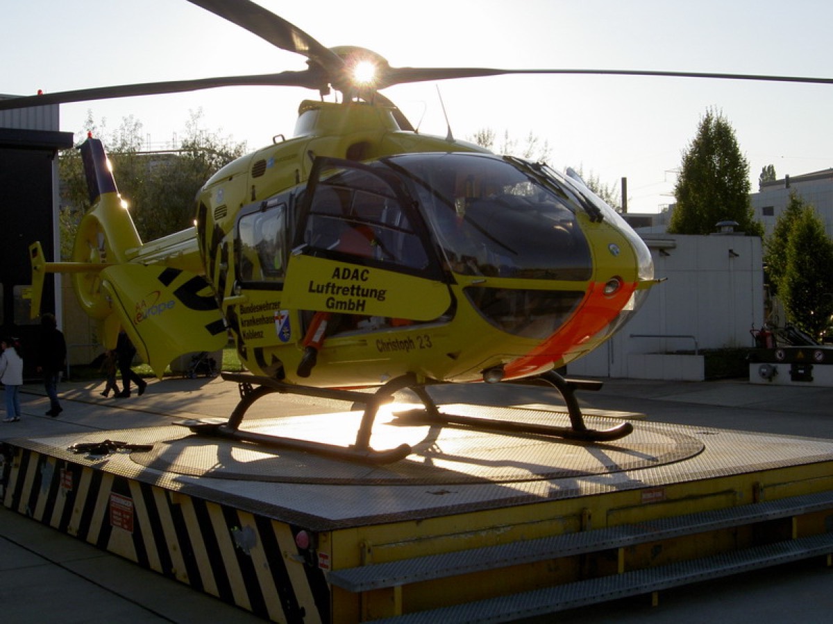
Christoph Meuer / Wikimedia CommonsCC BY 2.0 DE
RotaryModern
AIRCRAFT BRIEF
The Eurocopter EC135 (now Airbus H135) is a twin-engine light utility helicopter that first flew in 1994 and entered service in 1996. Developed from the MBB Bo 108 prototype, it features an innovative four-blade hingeless composite main rotor and a Fenestron enclosed tail rotor, making it the quietest helicopter in its class. Over 1,400 have been delivered to 300 operators in 60 countries, primarily serving in EMS, law enforcement, and corporate transport roles.
RANGE VISUALIZER
SPECIFICATIONS
manufacturerEurocopter (Airbus Helicopters)
first Flight1994
roleLight twin utility helicopter
crew1–2 pilots + 6 passengers
engines2x Turbomeca Arrius 2B1 (583 shp each)
max Speed287 km/h (155 kts)
range620 km (335 nmi)
ceiling20,000 ft
weight2,835 kg (MTOW)
PHS 1 — Pre-Flight Planning9 steps
| 01 | Mission BriefingNOTE: Define mission type, route, LZs, alternates, and crew roles. | COMPLETED | |
| 02 | Weather Briefing (METAR / TAF / Winds)CAUTION: Wind is critical for helicopter ops. Check surface winds, gusts, and wind shear at all LZs. | REVIEWED | |
| 03 | NOTAMsNOTE: Check for TFRs, restricted areas, heliport closures, and obstacles along route. | REVIEWED | |
| 04 | Fuel Planning (Hover Time Included)NOTE: Fuel burn approx 200 kg/hr cruise. Include hover time at departure and destination plus 20-min VFR reserve. | CALCULATED | |
| 05 | Weight & Balance / PayloadCAUTION: MTOW 2,631 kg. Verify CG is within fore-aft and lateral limits with all passengers and cargo loaded. | WITHIN LIMITS | |
| 06 | Performance Planning (Density Altitude / Hover Ceiling)WARNING: Service ceiling ~20,000 ft. Verify IGE/OGE hover capability at departure and destination elevations for ambient temperature. | CALCULATED | |
| 07 | Route / Landing Zone SurveyNOTE: Review LZ dimensions, approach/departure paths, obstacles, surface type, and slope. | COMPLETED | |
| 08 | Radio Frequencies & Transponder CodesNOTE: Record ATIS, tower, approach, enroute, and destination frequencies. Set transponder code. | NOTED | |
| 09 | GSX - Fuel TruckNOTE: GSX menu: Refuel Aircraft. Note: GSX fuel support varies by airport and helipad. | REFUEL COMPLETE |
PHS 2 — Cockpit Preparation / Before Start16 steps
| 01 | Preflight Walk-AroundNOTE: Inspect main rotor blades, Fenestron, engine intakes/exhausts, pitot/static ports, landing gear, and fuel drains. | COMPLETED | |
| 02 | Rotor AreaWARNING: Ensure all persons and obstacles are clear of the rotor disc and Fenestron. | CLEAR | |
| 03 | Doors | CLOSED AND LATCHED | |
| 04 | Seats and Harnesses | ADJUSTED AND LOCKED | |
| 05 | Circuit BreakersNOTE: Check overhead and side panels. All breakers should be flush. | ALL IN | |
| 06 | Fuel QuantityNOTE: Verify fuel quantity on gauges matches planned fuel load. | CHECKED - SUFFICIENT FOR FLIGHT | |
| 07 | Collective | FULL DOWN AND LOCKED | |
| 08 | Throttle (Twist Grip) | CLOSED (IDLE STOP) | |
| 09 | Battery Master Switch | ON | |
| 10 | External Power (if connected)NOTE: Use GPU for extended ground ops to preserve battery. | ON / AS REQUIRED | |
| 11 | Caution / Advisory PanelCAUTION: Press test button. All warning, caution, and advisory lights should illuminate. Verify no unexpected faults remain. | CHECK AND TEST | |
| 12 | Fuel Pump SwitchesNOTE: Both left and right fuel boost pumps. | ON | |
| 13 | Engine 1 and Engine 2 Start Switches | OFF | |
| 14 | Rotor Brake | ENGAGED | |
| 15 | Anti-Ice / De-IceNOTE: Set engine intake and pitot heat based on conditions. | AS REQUIRED | |
| 16 | Beacon LightWARNING: Beacon must be ON before engine start to warn ground crew. | ON |
PHS 3 — Engine 1 Start10 steps
| 01 | Area Around HelicopterWARNING: Final visual check. Call 'CLEAR TO START' to ground crew. | CLEAR | |
| 02 | Engine 1 Start SwitchNOTE: FADEC controls the automated start sequence. Hold until N1 rises. | ON | |
| 03 | Engine 1 N1NOTE: N1 should begin to accelerate within a few seconds. | MONITOR - RISING | |
| 04 | Engine 1 TOTWARNING: TOT must not exceed start limit (927 deg C max for start). Be ready to abort if TOT rises abnormally. | MONITOR - WITHIN LIMITS | |
| 05 | Engine 1 Oil PressureWARNING: Oil pressure must register within 30 seconds. Abort start if no indication. | CHECK - RISING | |
| 06 | Engine 1 N1 StabilizationNOTE: Wait for N1 to stabilize at ground idle. FADEC manages fuel scheduling. | IDLE - STABILIZED | |
| 07 | Engine 1 FLI (First Limit Indicator)NOTE: FLI replaces traditional torque/TOT gauges. Should indicate well within limits at idle. | CHECK - GREEN RANGE | |
| 08 | Engine 1 Generator | ON | |
| 09 | Rotor BrakeNOTE: Release rotor brake once Engine 1 is stable at idle. Nr will begin to increase. | RELEASE | |
| 10 | Nr (Rotor RPM)NOTE: Nr will spool up toward 100% (394-395 RPM). Do not start Engine 2 until Nr is stabilized. | MONITOR - INCREASING |
PHS 4 — Engine 2 Start11 steps
| 01 | Engine 1 ParametersNOTE: Confirm Engine 1 oil pressure, TOT, N1, and FLI are normal before starting Engine 2. | STABLE - ALL IN GREEN | |
| 02 | Engine 2 Start SwitchNOTE: FADEC controls start sequence. Hold until N1 rises. | ON | |
| 03 | Engine 2 N1 | MONITOR - RISING | |
| 04 | Engine 2 TOTWARNING: Same TOT start limit applies. Abort if overtemp. | MONITOR - WITHIN LIMITS | |
| 05 | Engine 2 Oil PressureWARNING: Must register within 30 seconds. | CHECK - RISING | |
| 06 | Engine 2 N1 Stabilization | IDLE - STABILIZED | |
| 07 | Engine 2 FLI | CHECK - GREEN RANGE | |
| 08 | Engine 2 Generator | ON | |
| 09 | Both FLI NeedlesNOTE: Both FLI needles should indicate nearly identical values, confirming balanced engine output. | JOINED - MATCHED | |
| 10 | Nr / N2 Display (Three Needles)CAUTION: Nr and both N2 needles should converge at 100%. Any split greater than 2% requires investigation. | 100% - ALL MATCHED | |
| 11 | External Power (if connected) | DISCONNECT |
PHS 5 — Post-Start / Systems Check13 steps
| 01 | Avionics Master | ON | |
| 02 | PFD / MFDNOTE: Verify primary flight display and multifunction display are showing correct data. | CHECK - POWERED AND OPERATIONAL | |
| 03 | Attitude Indicator | ERECT AND CORRECT | |
| 04 | Heading Indicator / HSI | SET TO MAGNETIC HEADING | |
| 05 | AltimeterNOTE: Cross-check with known field elevation. | SET TO LOCAL QNH | |
| 06 | Radio Altimeter | CHECK - SET BUGS AS REQUIRED | |
| 07 | AFCS (Autopilot / SAS)NOTE: If equipped with autopilot or stability augmentation system, engage and verify self-test. | ON - SELF-TEST PASSED | |
| 08 | COM RadiosNOTE: Set frequencies and perform radio check with ATC or ground. | SET - CHECK TX/RX | |
| 09 | NAV / GPS | SET - FLIGHT PLAN LOADED | |
| 10 | Transponder | SET CODE - STANDBY | |
| 11 | Caution / Advisory PanelNOTE: All caution and warning lights should be extinguished at this point. | NO WARNINGS - CLEAR | |
| 12 | Hydraulic SystemNOTE: Duplex hydraulic system (tandem piston). Verify both systems show normal pressure. | PRESSURE - NORMAL | |
| 13 | Fuel BalanceNOTE: Left and right tanks should be balanced within limits. | CHECK - BALANCED |
PHS 6 — Before Taxi / Hover Check10 steps
| 01 | Flight Controls - CyclicNOTE: Full deflection in all axes. Check for smooth movement and correct response. | FREE AND CORRECT | |
| 02 | Flight Controls - Collective | FREE AND CORRECT | |
| 03 | Flight Controls - Anti-Torque PedalsNOTE: Fenestron response should be smooth through full range. | FREE AND CORRECT | |
| 04 | Trim | SET - NEUTRAL / AS REQUIRED | |
| 05 | Duplex Hydraulic System TestCAUTION: Test each hydraulic system individually. Control forces increase significantly with a system OFF. Return both to ON. | BOTH SYSTEMS NORMAL | |
| 06 | CollectiveNOTE: Establish a 3-5 ft hover. Note power required vs available. | RAISE SLOWLY TO LIGHT ON SKIDS | |
| 07 | Hover Power CheckCAUTION: Verify FLI is in green arc. If power required approaches FLI limit, reassess payload or conditions. | WITHIN LIMITS | |
| 08 | Engine Instruments in HoverNOTE: Check both engines: FLI, N1, Nr, TOT, oil pressure and temperature. | ALL GREEN | |
| 09 | Yaw Pedals in HoverNOTE: Check adequate yaw control in both directions. Verify Fenestron effectiveness. | FENESTRON AUTHORITY - ADEQUATE | |
| 10 | Caution Panel in Hover | CLEAR - NO WARNINGS |
PHS 7 — Taxi5 steps
| 01 | Taxi ClearanceNOTE: Contact ground/tower for taxi instructions if at controlled field. | OBTAINED | |
| 02 | Landing Light | ON | |
| 03 | Taxi SpeedCAUTION: Maintain slow hover-taxi. Avoid downwash effects on other aircraft or personnel. | WALKING PACE - MAX 10 KTS | |
| 04 | Hover HeightNOTE: Maintain a stable hover-taxi height. Avoid exceeding skid height limits. | 3-5 FEET AGL | |
| 05 | Obstacle Clearance | CONFIRM - ROTOR AND FENESTRON CLEAR |
PHS 8 — Before Takeoff7 steps
| 01 | Takeoff Clearance | OBTAINED | |
| 02 | Transponder | ALT (Mode C/S) | |
| 03 | Navigation Lights / Strobes | ON | |
| 04 | Engine Instruments | ALL GREEN - BOTH ENGINES | |
| 05 | Wind CheckNOTE: Confirm wind direction and speed for departure path selection. | NOTED | |
| 06 | Departure PathWARNING: Plan departure route to maintain safe single-engine performance if possible. | CLEAR OF OBSTACLES | |
| 07 | Passenger BriefNOTE: Doors, belts, no smoking, emergency procedures. | COMPLETED |
PHS 9 — Takeoff6 steps
| 01 | CollectiveNOTE: Raise collective to accelerate into a climbing departure. Transition through ETL (16-24 kts). | INCREASE SMOOTHLY | |
| 02 | Pedals | COORDINATE - TRIM BALL CENTERED | |
| 03 | CyclicNOTE: Establish positive rate of climb and accelerate to Vy (best rate of climb speed). | NOSE FORWARD - ACCELERATE | |
| 04 | FLIWARNING: Do not exceed FLI continuous or transient limits during takeoff. | WITHIN LIMITS | |
| 05 | Airspeed - Passing Through ETLNOTE: Expect vibration and increased lift as you pass through effective translational lift. | 16-24 KIAS - TRANSITION COMPLETE | |
| 06 | Positive Rate of Climb | CONFIRMED - VSI POSITIVE |
PHS 10 — Climb6 steps
| 01 | AirspeedNOTE: Maintain best rate of climb speed or as required for obstacle clearance. | 80-100 KIAS | |
| 02 | FLI | WITHIN CONTINUOUS LIMITS | |
| 03 | Engine Instruments | ALL GREEN - BOTH ENGINES | |
| 04 | NrCAUTION: Nr should remain at 100% throughout climb. Any droop requires immediate attention. | 100% | |
| 05 | Altimeter | CROSSCHECK - CLIMBING TO ASSIGNED ALTITUDE | |
| 06 | Fuel Balance | MONITORING |
PHS 11 — Cruise9 steps
| 01 | Level Off at Cruise Altitude | SET ATTITUDE AND POWER | |
| 02 | AirspeedWARNING: Vne is 140 KIAS. Never exceed.NOTE: Normal cruise approximately 137 KIAS. Adjust for conditions. | 130-137 KIAS | |
| 03 | FLI | CRUISE POWER - GREEN ARC | |
| 04 | Engine Instruments | ALL GREEN - SCAN REGULARLY | |
| 05 | Nr / N2 | 100% - MATCHED | |
| 06 | Fuel Quantity and Balance | MONITOR - LOG PERIODICALLY | |
| 07 | Navigation | ON TRACK - CROSSCHECK GPS AND MAP | |
| 08 | AFCS (if engaged) | MONITOR - VERIFY FUNCTION | |
| 09 | Caution / Advisory Panel | CLEAR |
PHS 12 — Descent / Approach7 steps
| 01 | ATIS / Weather at DestinationNOTE: Get current weather and active approach information. | OBTAINED | |
| 02 | Altimeter | SET TO DESTINATION QNH | |
| 03 | Approach BriefingNOTE: Brief approach type, LZ layout, obstacles, go-around plan, and wind. | COMPLETED | |
| 04 | AirspeedNOTE: Begin deceleration for approach. | REDUCING - 80-100 KIAS | |
| 05 | Descent Rate | 500-700 FPM - AS REQUIRED | |
| 06 | Radio Altimeter | MONITOR - CALLOUTS AS REQUIRED | |
| 07 | Landing Light | ON |
PHS 13 — Before Landing5 steps
| 01 | Landing Clearance | OBTAINED | |
| 02 | Landing Zone / HelipadCAUTION: Verify LZ is clear of debris, vehicles, and personnel. | CLEAR - CONFIRMED | |
| 03 | Wind Direction and SpeedNOTE: Land into the wind when possible. | NOTED | |
| 04 | Approach AngleWARNING: Maintain safe approach angle. Avoid steep approaches unless required by terrain. | NORMAL - CLEAR OF OBSTACLES | |
| 05 | Airspeed - Decelerating | BELOW 40 KIAS - TRANSITIONING TO HOVER |
PHS 14 — Landing5 steps
| 01 | Establish Hover | 3-5 FEET AGL - STABILIZED | |
| 02 | Wind Drift / Position | CORRECTED - OVER INTENDED SPOT | |
| 03 | FLI Check in Hover | WITHIN LIMITS | |
| 04 | CollectiveNOTE: Maintain heading with pedals throughout. | LOWER SMOOTHLY - TOUCH DOWN GENTLY | |
| 05 | Confirm on Ground | STABLE - ALL SKIDS FIRMLY ON SURFACE |
PHS 15 — After Landing6 steps
| 01 | Collective | FULL DOWN | |
| 02 | Transponder | STANDBY | |
| 03 | Landing / Strobe Lights | OFF - AS REQUIRED | |
| 04 | Navigation Lights | AS REQUIRED | |
| 05 | AFCS / Autopilot | OFF | |
| 06 | ATC / Ground | CONTACT - ADVISE ON THE GROUND |
PHS 16 — Shutdown / Securing17 steps
| 01 | Throttle (Twist Grip) | IDLE | |
| 02 | Engine 2 Start SwitchNOTE: Shut down Engine 2 first. Monitor Engine 1 assumes full load. | OFF | |
| 03 | Engine 2 TOT and N1 | DECREASING - SPOOLING DOWN | |
| 04 | Engine 1 Parameters (Single-Engine)CAUTION: Monitor Engine 1 as it assumes full Nr governance. FLI should remain in green. | STABLE - WITHIN LIMITS | |
| 05 | Wait for Engine 2 Complete ShutdownNOTE: Allow 30-60 seconds for full spool-down. | N1 - ZERO / TOT - DECREASING | |
| 06 | Engine 1 Start Switch | OFF | |
| 07 | Engine 1 TOT and N1 | DECREASING - SPOOLING DOWN | |
| 08 | Nr (Rotor RPM)CAUTION: Do not apply rotor brake until Nr drops below 50%. | DECREASING | |
| 09 | Rotor BrakeWARNING: Applying rotor brake above 50% Nr can damage the braking system. | APPLY - BELOW 50% Nr | |
| 10 | Nr | ZERO - ROTOR STOPPED | |
| 11 | Avionics Master | OFF | |
| 12 | All Electrical Equipment | OFF | |
| 13 | Fuel Boost Pumps | OFF | |
| 14 | Generator Switches | OFF | |
| 15 | Battery Master Switch | OFF | |
| 16 | Beacon Light | OFF | |
| 17 | Secure CockpitNOTE: Apply gust lock if required. Install blade tie-downs in windy conditions. Close and lock all doors. | COMPLETED |