Bell UH-1H HueyMSFS 2024 Startup Checklist · 128 steps
Bell UH-1H Huey
MSFS 2024 - 0/128 STEPS
U.S. Army / Wikimedia CommonsPublic Domain
RotaryVietnam Era
AIRCRAFT BRIEF
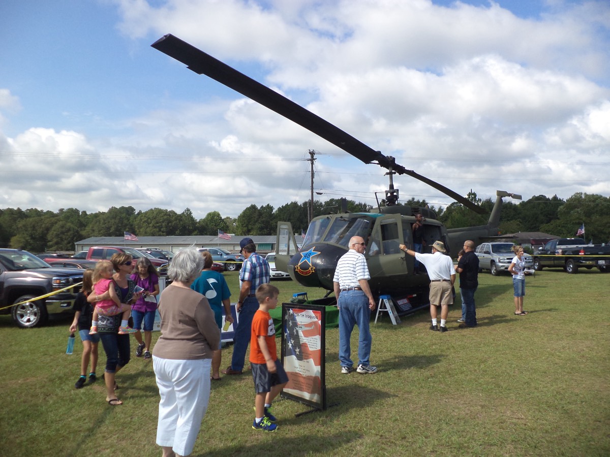
The Bell UH-1 Iroquois, universally known as the 'Huey,' is the most iconic helicopter in military history. Over 16,000 were built starting in 1959, and it became the symbol of the Vietnam War. The UH-1H variant featured the more powerful T53-L-13B engine. Taog's Hangar brings this legendary aircraft to MSFS 2024 with detailed systems modeling and authentic flight dynamics that capture the Huey's unique character.
RANGE VISUALIZER
SPECIFICATIONS
manufacturerBell Helicopter (Taog's Hangar)
first Flight1959
roleUtility helicopter
crew1–4 crew + 12–14 troops
engines1x Lycoming T53-L-13B (1,400 shp)
max Speed241 km/h (130 kts)
range510 km (275 nmi)
ceiling16,100 ft
weight4,309 kg (MTOW)
PHS 1 — Pre-Flight Planning9 steps
| 01 | Mission BriefNOTE: Review flight plan, destination, passenger/cargo manifest, and mission objectives. | REVIEWED | |
| 02 | Weather BriefingNOTE: Check METAR/TAF at departure and destination. Wind direction critical for helicopter approach planning. | REVIEWED | |
| 03 | NOTAMs / AirspaceNOTE: Check for TFRs, heliport closures, restricted areas, and airspace restrictions along route. | REVIEWED | |
| 04 | Fuel PlanningNOTE: Plan fuel for mission duration plus 20-minute reserve. Factor in hover time at destination. Burn rate ~80 GPH at cruise. | CALCULATED | |
| 05 | Weight & Balance / PayloadCAUTION: Max gross weight 9,500 lbs. Account for passengers, cargo, and fuel. CG position critical for hover stability. | WITHIN LIMITS | |
| 06 | Performance PlanningNOTE: Check density altitude - determines hover ceiling and max payload. High/hot conditions degrade performance significantly. | CHECKED | |
| 07 | Route / Landing Zone SurveyNOTE: Review landing zone size, obstacles, approach/departure paths, and alternate landing sites. | REVIEWED | |
| 08 | Radio FrequenciesNOTE: Set COM1/COM2 frequencies. Note tower, approach, CTAF, and enroute frequencies. | SET | |
| 09 | GSX - Fuel TruckNOTE: GSX menu: Refuel Aircraft. Note: GSX fuel support varies by airport and helipad. | REFUEL COMPLETE |
PHS 2 — Electrical / Pre-Start8 steps
| 01 | Circuit Breakers | CHECK - All in | |
| 02 | Battery Switch | ON | |
| 03 | Main Generator Switch | ON | |
| 04 | Non-Essential Bus | ON | |
| 05 | Inverter SwitchNOTE: AC power off until after engine start. | OFF | |
| 06 | Caution Panel - Low RPM WarningCAUTION: Reset the low RPM warning before starting to prevent audio alert. | PRESS TO RESET | |
| 07 | Governor SwitchNOTE: Will be set to AUTO before engine start sequence. | OFF (Center) | |
| 08 | Pitot Heat | OFF |
PHS 3 — Engine Setup7 steps
| 01 | Governor SwitchNOTE: AUTO allows governor to maintain 6,600 RPM in flight. | AUTO (Forward) | |
| 02 | Main Fuel Switch | ON (Forward) | |
| 03 | Chip Detector SwitchNOTE: Monitors for metal particles in engine and transmission oil. | BOTH (Forward) | |
| 04 | Force Trim Switch | ON (Forward) | |
| 05 | Hydraulic Control Switch | ON (Forward) | |
| 06 | CollectiveCAUTION: Collective must be fully lowered before engine start to prevent uncontrolled lift. | FULL DOWN | |
| 07 | ThrottleNOTE: Press idle release button to move throttle past the idle stop detent. | CLOSE - Rotate to idle stop position |
PHS 4 — Engine Start9 steps
| 01 | Area Around HelicopterWARNING: Visually confirm no persons or obstacles near rotor disc area. | CLEAR | |
| 02 | Starter ButtonNOTE: Hold starter until N1 reaches 40%. | PRESS AND HOLD | |
| 03 | N1 RPM | MONITOR - Rotors begin turning at ~15% N1 | |
| 04 | Starter Button | RELEASE AT 40% N1 | |
| 05 | EGTWARNING: EGT must not exceed 400°C during start. Exceeding 610°C causes engine damage - abort start immediately. | MONITOR | |
| 06 | ThrottleCAUTION: Advance throttle gradually - sudden movement risks overtorque or compressor stall. | SLOWLY ADVANCE TO FULL OPEN AT 70% N1 | |
| 07 | N2 / Rotor RPMNOTE: Governor auto-maintains RPM. N1 and N2 needles should be married (matched). | STABILIZE AT 6,600 RPM (324 ROTOR) | |
| 08 | Oil PressureWARNING: If oil pressure does not rise within 30 seconds of start, shut down immediately. | CHECK - 40–70 PSI | |
| 09 | EGT (Stabilized) | CHECK - Below 400°C at idle |
PHS 5 — Post-Start / Systems9 steps
| 01 | Inverter SwitchNOTE: Enables AC power for instruments. | MAIN ON | |
| 02 | Gyro / Attitude IndicatorNOTE: Allow 2–3 minutes for gyros to spin up. | CHECK - Erect and stable | |
| 03 | Compass | SET HEADING | |
| 04 | Altimeter | SET - Field elevation / QNH | |
| 05 | Radios (COM1 / COM2) | SET FREQUENCIES | |
| 06 | Transponder | SET CODE - STANDBY | |
| 07 | Navigation Instruments | SET AS REQUIRED | |
| 08 | Caution Panel | CHECK - No warnings | |
| 09 | Engine InstrumentsNOTE: Torque, EGT, N1, N2, oil pressure, oil temperature. | CHECK - All in green |
PHS 6 — Before Taxi / Hover Check11 steps
| 01 | Flight ControlsNOTE: Cyclic, collective, and pedals - full travel in all directions. | CHECK - Free and correct | |
| 02 | Force Trim | CHECK - Functional | |
| 03 | DoorsNOTE: Or open as required for mission. Ensure doors are secured. | CLOSED AND LATCHED | |
| 04 | Crew / PassengersNOTE: Brief emergency exits, seatbelts, and no-touch zones near controls. | BRIEFED AND SECURE | |
| 05 | Anti-Collision Light | ON | |
| 06 | Position Lights | AS REQUIRED | |
| 07 | Landing Light | AS REQUIRED | |
| 08 | Hover Check - CollectiveCAUTION: Monitor torque - do not exceed limits. If power margin insufficient, reduce payload. | RAISE SLOWLY TO HOVER | |
| 09 | Hover Check - Left PedalNOTE: Huey torques right - add left pedal as collective increases. | ADD TO COUNTER TORQUE | |
| 10 | Hover Check - StabilizeNOTE: Verify engine instruments in limits, check power margin. | 3–5 FT AGL - IN GROUND EFFECT | |
| 11 | Hover Check - Engine Instruments | CHECK - Torque, EGT, RPM in limits |
PHS 7 — Taxi5 steps
| 01 | Area Clear | CHECK - Clear all sides | |
| 02 | Hover TaxiNOTE: Walking pace - maintain 3–5 ft AGL, below translational lift speed. | FORWARD CYCLIC GENTLY | |
| 03 | PedalsNOTE: Use pedals to maintain heading - do not use cyclic for yaw corrections. | MAINTAIN HEADING | |
| 04 | ObstaclesCAUTION: Be aware of tail rotor clearance from obstacles and personnel. | MONITOR - Maintain clearance | |
| 05 | Ground Taxi (Alternative)NOTE: Only on smooth, level surfaces. Keep RPM at 6,600. | LOW COLLECTIVE - SKIDS ON GROUND |
PHS 8 — Before Takeoff7 steps
| 01 | Engine InstrumentsNOTE: Torque, EGT, N1, N2, oil pressure, oil temperature. | CHECK - ALL GREEN | |
| 02 | Fuel Quantity | CHECK - Adequate for flight | |
| 03 | Caution Panel | CLEAR - No warnings | |
| 04 | Transponder | SET AND ON (ALT) | |
| 05 | Radios | SET - Contact tower / CTAF | |
| 06 | Wind Check | NOTE - Takeoff into wind preferred | |
| 07 | Departure Path | CLEAR OF OBSTACLES |
PHS 9 — Takeoff6 steps
| 01 | CollectiveCAUTION: Monitor torque - do not exceed 48 PSI. | INCREASE SMOOTHLY | |
| 02 | Pedals | MAINTAIN HEADING | |
| 03 | CyclicNOTE: Expect slight vibration and left yaw at Effective Translational Lift (~15 kts). | FORWARD - Accelerate through ETL | |
| 04 | Translational LiftNOTE: Helicopter becomes more efficient - reduce collective slightly as lift increases. | FEEL - Aircraft climbs at ~16–24 kts | |
| 05 | Climb SpeedNOTE: Best climb speed for the Huey. | ESTABLISH 60–70 KTS | |
| 06 | Climb RateNOTE: Adjust collective and cyclic for desired climb rate. | 500–1,000 FT/MIN |
PHS 10 — Climb5 steps
| 01 | AirspeedNOTE: Best rate of climb speed. | 60–70 KTS (Vy) | |
| 02 | Engine Instruments | MONITOR - All in limits | |
| 03 | TorqueCAUTION: Prolonged operation above 40 PSI shortens engine life. | MONITOR - Max continuous 40 PSI | |
| 04 | Altimeter | CHECK - Set QNH or standard | |
| 05 | Landing Light | OFF (above 500 ft AGL) |
PHS 11 — Cruise7 steps
| 01 | Altitude | AT ASSIGNED LEVEL | |
| 02 | AirspeedNOTE: VNE 120 kts. Adjust for mission and conditions. | 80–100 KTS (NORMAL CRUISE) | |
| 03 | TorqueNOTE: Typically 30–35 PSI in cruise. | SET - CRUISE POWER | |
| 04 | Fuel State | MONITOR - Check quantity and burn rate | |
| 05 | Navigation | CHECK - Heading, GPS, position | |
| 06 | Engine Instruments | SCAN - Regular instrument cross-check | |
| 07 | TrimNOTE: Use force trim to relieve control pressure. | ADJUST AS NEEDED |
PHS 12 — Descent / Approach10 steps
| 01 | Airspeed | 80–90 KTS DESCENT SPEED | |
| 02 | CollectiveCAUTION: Avoid rapid collective reduction - may cause rotor RPM droop below 6,600. | REDUCE FOR DESCENT | |
| 03 | Rate of Descent | 300–500 FT/MIN NORMAL | |
| 04 | Altimeter | SET - LOCAL QNH | |
| 05 | Landing Zone | IDENTIFY - Wind direction, obstacles, surface | |
| 06 | Landing Light | ON | |
| 07 | Airspeed | REDUCE - Decelerate to 40–60 kts on approach | |
| 08 | Approach AngleNOTE: Aim for a constant angle - typically 8–12 degrees. | MAINTAIN - Steady approach to landing point | |
| 09 | Pedals | MAINTAIN HEADING ALIGNMENT | |
| 10 | DecelerateCAUTION: Do not flare too aggressively - risk of tail strike with low skid clearance. | AFT CYCLIC - Reduce to hover speed |
PHS 13 — Before Landing4 steps
| 01 | Landing ZoneNOTE: Check for obstacles, wires, debris, and personnel. | CONFIRMED CLEAR | |
| 02 | Wind | FINAL CHECK - Note direction and speed | |
| 03 | Engine Instruments | CHECK - All in limits | |
| 04 | Passengers / Cargo | SECURE |
PHS 14 — Landing7 steps
| 01 | HoverNOTE: Stabilize in ground effect before landing. | ESTABLISH AT 3–5 FT AGL | |
| 02 | Drift | CHECK - Correct any drift with cyclic | |
| 03 | CollectiveNOTE: Gentle descent - let skids touch evenly. | SLOWLY LOWER | |
| 04 | Touchdown | SKIDS ON GROUND - LEVEL ATTITUDE | |
| 05 | Collective | FULL DOWN AFTER TOUCHDOWN | |
| 06 | Cyclic | NEUTRAL | |
| 07 | Pedals | NEUTRAL |
PHS 15 — After Landing5 steps
| 01 | Transponder | STANDBY | |
| 02 | Landing Light | OFF | |
| 03 | Anti-Collision LightNOTE: Keep anti-collision light on while rotors are turning. | ON | |
| 04 | Engine Instruments | CHECK - All normal | |
| 05 | Radios | AS REQUIRED |
PHS 16 — Shutdown / Securing19 steps
| 01 | Collective | FULL DOWN | |
| 02 | ThrottleNOTE: Let engine cool for 2 minutes at idle before shutdown. | CLOSE TO IDLE | |
| 03 | Avionics / Radios | OFF | |
| 04 | Transponder | OFF | |
| 05 | Navigation Equipment | OFF | |
| 06 | Inverter | OFF | |
| 07 | ThrottleCAUTION: Wait for N1 RPM to drop below 40% before turning off fuel. | CLOSE - ROTATE TO OFF | |
| 08 | Main Fuel Switch | OFF | |
| 09 | N1 / N2 RPM | MONITOR - Wait for full spool-down | |
| 10 | Force Trim | OFF | |
| 11 | Hydraulic Control | OFF | |
| 12 | Governor Switch | OFF (Center) | |
| 13 | Non-Essential Bus | OFF | |
| 14 | Main Generator | OFF | |
| 15 | Battery Switch | OFF | |
| 16 | Anti-Collision Light | OFF | |
| 17 | All Lights | OFF | |
| 18 | Rotor BrakeWARNING: Never apply rotor brake above 30% RPM - causes rotor system damage. | APPLY WHEN RPM BELOW 30% | |
| 19 | Tie-Down / ChocksNOTE: Secure main rotor blade and install tie-downs if parking. | SECURE |