F-16C Block 50FALCON BMS Startup Checklist · 66 steps
F-16C Block 50
FALCON BMS - 0/66 STEPS
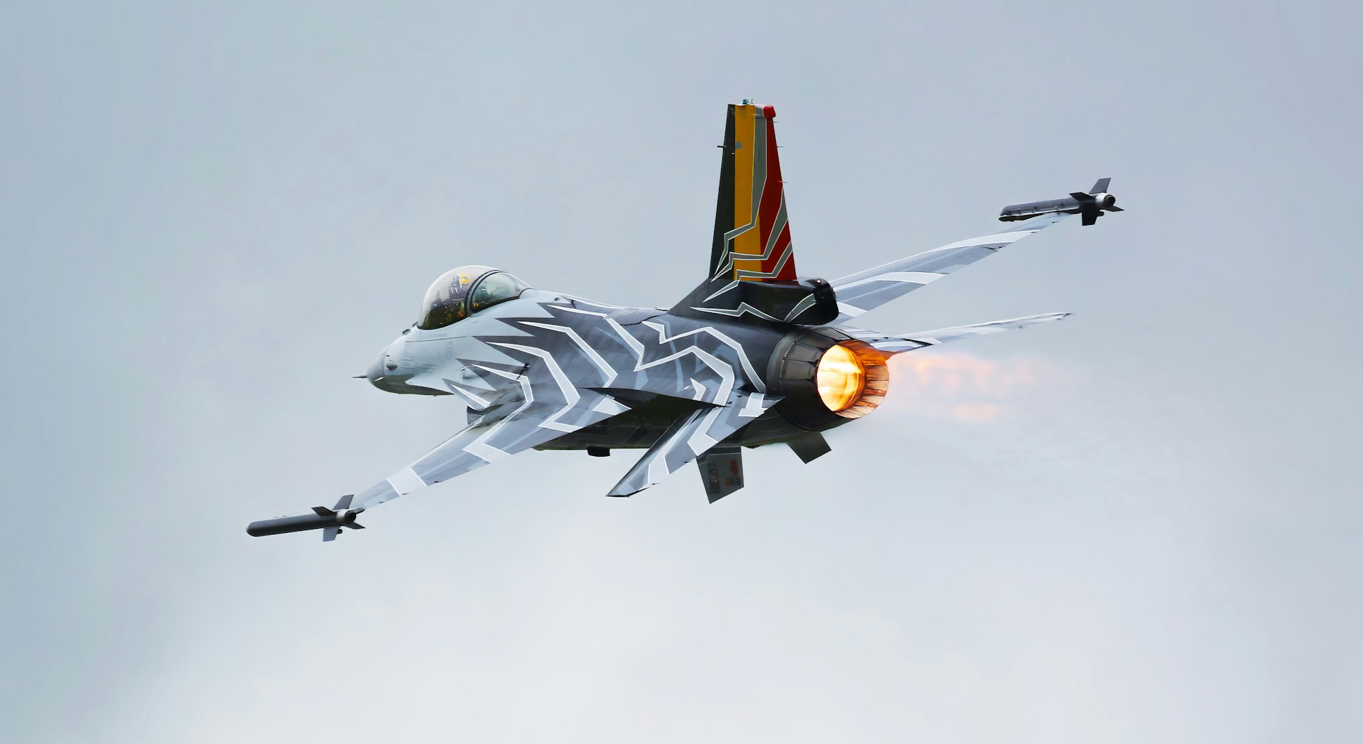
UnsplashUnsplash License
Fighter4th Gen
AIRCRAFT BRIEF
Falcon BMS (Benchmark Sims) is a community-developed, standalone total conversion of Falcon 4.0 - Microprose's legendary 1998 F-16 simulation. BMS has been in continuous development for over 20 years and represents one of the most realistic and feature-complete fighter simulations ever made. The F-16C Block 50 is the primary variant, modelling the GE F110-powered airframe with APG-68 radar, HTS, LANTIRN/Sniper pods, and full HARM employment. BMS is available free to anyone who owns Falcon 4.0.
SPECIFICATIONS
manufacturerGeneral Dynamics / Lockheed Martin
first Flight1974
roleMultirole fighter
crew1 pilot
engines1x GE F110-GE-129 (29,500 lbf with A/B)
max Speed2,120 km/h (Mach 2.0)
range4,220 km (2,280 nmi, clean)
ceiling50,000+ ft
weight21,772 kg (MTOW)
PHS 1 — Pre-Flight Planning8 steps
| 01 | Mission BriefNOTE: Review mission type, objectives, ROE, threat environment, and timeline. | REVIEWED | |
| 02 | Weather BriefingNOTE: Check departure, target area, and recovery weather. Note icing levels. | REVIEWED | |
| 03 | NOTAMs / AirspaceNOTE: Check restricted areas, active MOAs, and NOTAM restrictions. | REVIEWED | |
| 04 | Fuel Planning - Bingo / JokerNOTE: Calculate bingo fuel (min to RTB) and joker fuel (leave target area). Single-engine - fuel management is critical. | SET | |
| 05 | Stores / LoadoutNOTE: Confirm weapons, pylons, pods, and external tanks match mission requirements. | VERIFIED | |
| 06 | Data Cartridge (DC)NOTE: Verify DC contains correct steerpoints, threats, radios, and IFF codes for the mission. | LOADED | |
| 07 | Radio Frequencies / IFFNOTE: Set UHF/VHF presets. Confirm IFF Mode 1/2/3/4 codes. Brief EMCON restrictions. | SET | |
| 08 | Divert BasesNOTE: Know nearest divert fields, runway lengths, and approach frequencies. | IDENTIFIED |
PHS 2 — Electrical Power7 steps
| 01 | Main Power SwitchNOTE: Applies battery power. Cockpit will partially illuminate. | BATT | |
| 02 | CanopyNOTE: Ensure canopy is fully latched before applying main power. | CLOSE & LOCK | |
| 03 | Main Power SwitchNOTE: Applies main electrical bus power. | MAIN PWR | |
| 04 | Oxygen Supply Lever | ON | |
| 05 | Fuel Master SwitchWARNING: Engine cannot receive fuel without this switch. | MASTER (Guard Up) | |
| 06 | ENG FEED Knob | NORM | |
| 07 | Cockpit Lighting | SET AS NEEDED |
PHS 3 — Avionics Power-Up10 steps
| 01 | Avionics Power KnobNOTE: Wait ~30 seconds for avionics to initialise before proceeding. | ON | |
| 02 | MMC Switch | MMC | |
| 03 | ST STA Switch | ST STA | |
| 04 | MFD Switch | MFD | |
| 05 | UFC Switch | UFC | |
| 06 | GPS Switch | GPS | |
| 07 | DL Switch | DL | |
| 08 | Master Arm | SAFE | |
| 09 | Left HDPT SwitchNOTE: Hardpoint switches - off during startup. | OFF | |
| 10 | Right HDPT Switch | OFF |
PHS 4 — Before Engine Start6 steps
| 01 | ThrottleWARNING: Throttle must be in CUTOFF before JFS activation. | CUTOFF | |
| 02 | STORES CONFIG SwitchNOTE: Set based on external stores loaded. | CAT I or CAT III | |
| 03 | Anti-Ice Switch | AS REQUIRED | |
| 04 | Seat Arm HandleCAUTION: Ensure area is clear before arming ejection seat. | ARMED | |
| 05 | Parking Brake | SET | |
| 06 | Wheel Chocks | IN PLACE (Confirm with Crew Chief) |
PHS 5 — Engine Start (JFS)9 steps
| 01 | JFS SwitchNOTE: Jet Fuel Starter activates. Listen for JFS spool-up. | START 2 | |
| 02 | JFS RPMNOTE: Wait for JFS to reach operating speed before advancing throttle. | STABILISED (~100%) | |
| 03 | ThrottleNOTE: Advance to IDLE when JFS is at speed. Engine light-off should occur. | IDLE | |
| 04 | Engine RPMCAUTION: If no light-off by 20% RPM, retard throttle to CUTOFF immediately. | INCREASING | |
| 05 | Oil PressureWARNING: Shut down immediately if oil pressure does not rise. | RISING WITHIN 10 SEC | |
| 06 | Nozzle PositionNOTE: Nozzle should open wide then settle as engine accelerates. | 60–80% (SETTLING) | |
| 07 | Engine RPM at IDLENOTE: Allow engine to fully stabilise at idle. | ~62–65% | |
| 08 | JFS SwitchNOTE: JFS will cut out automatically once engine reaches idle. Verify JFS RUN light extinguishes. | OFF (Auto) | |
| 09 | FLCS BITNOTE: Press FLCS BIT button on left console. Flight control system self-test. | INITIATE |
PHS 6 — Post-Start Checks6 steps
| 01 | EPU SwitchCAUTION: Ensure EPU ARM light is extinguished. | NORM (Guard closed) | |
| 02 | FLCS BIT Light | EXTINGUISHED (Test Complete) | |
| 03 | Caution / Warning LightsNOTE: ADDRESS any remaining caution lights before proceeding. | ALL CLEAR | |
| 04 | Hydraulic Pressure (A & B) | 2,850–3,250 PSI | |
| 05 | FUEL QTYNOTE: Verify fuel quantity matches pre-flight plan. Check BINGO setting. | CHECK | |
| 06 | Engine instrumentsNOTE: Verify RPM, FTIT (Fanjet Turbine Inlet Temp), Nozzle %, Oil PSI all stable. | IN LIMITS |
PHS 7 — INS / Navigation Alignment8 steps
| 01 | INS KnobNOTE: Switch to NORM to begin full inertial alignment. Allow 4–8 minutes for full alignment. | NORM | |
| 02 | Data CartridgeNOTE: Insert DC into Data Transfer Equipment (DTE) slot. LOAD button light will extinguish when loaded. | INSERT & LOAD | |
| 03 | UFC - STPT 1NOTE: Confirm steerpoints match briefed coordinates. | VERIFY COORDINATES | |
| 04 | IFF Master KnobNOTE: Set IFF codes as briefed. | NORM | |
| 05 | IFF Mode 4 | ON (Code Loaded) | |
| 06 | TACANNOTE: Set TACAN channel for departure airfield. | T/R, Channel SET | |
| 07 | HSI Course / HeadingNOTE: Confirm correct bearing pointer and desired course. | SET | |
| 08 | INS Alignment StatusNOTE: Wait for ALIGN light on DED to show ALIGN or 8-ball to move. | ALIGNED (IFA or NAV) |
PHS 8 — Weapons & Sensors5 steps
| 01 | SMS (Stores Management System)NOTE: Check MFD SMS page. Confirm all stations match briefed weapons. | VERIFY LOADOUT | |
| 02 | Weapon Fuzing | SET AS BRIEFED | |
| 03 | FCR (Fire Control Radar)NOTE: Allow radar to warm up during alignment. Verify BIT pass on MFD. | ON / WARM UP | |
| 04 | EWS (Electronic Warfare)NOTE: Set chaff and flare programs per threat environment briefing. | PROGRAMS SET | |
| 05 | ECM PodNOTE: Allow warm-up time before ECM is operational. | ON (If equipped) |
PHS 9 — Before Taxi7 steps
| 01 | Radar AltimeterNOTE: Set low altitude warning as appropriate for departure. | ON, SET 200 FT | |
| 02 | AltimeterNOTE: Set baro altimeter to current QNH. Verify field elevation ±75 ft. | SET QNH / FIELD ELEVATION | |
| 03 | LightsNOTE: Nav lights on. Anti-collision as required. Taxi light on. | AS REQUIRED | |
| 04 | Flight ControlsNOTE: Full deflection check - stick fore/aft, left/right; rudder left/right. | CHECK FREE & CORRECT | |
| 05 | BrakesCAUTION: Test toe brakes before releasing parking brake. | CHECK | |
| 06 | Parking BrakeNOTE: Release when cleared to taxi. | RELEASE | |
| 07 | Nose Wheel Steering | ENGAGED (NWS light ON) |